Drain Downspout Extender,Gutter Downspout Extensions,Flexible Downspout Extender ZHEJIANG HAOCHUAN RUBBER &PLASTIC CO.,LTD , https://www.zjhaochuan.com
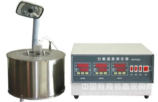
**Ignition Temperature Tester**
---
### I. Overview
The Ignition Temperature Tester is a specialized device designed and manufactured in accordance with the national petrochemical standard GB/T 5332, "Test Method for Flammable Liquid and Gas Ignition Temperature." It is used to determine the auto-ignition temperature of chemically pure flammable liquids and gases under atmospheric pressure conditions.
This instrument features multiple heating elements, including a high-temperature metal furnace, along with upper and lower covers. To accommodate testing of samples above 200°C, a stainless steel 200ml Erlenmeyer flask is included. The intelligent digital temperature controller ensures uniform heat distribution, fast heating, and precise control, which helps reduce testing time significantly.
To enhance visibility during the ignition process, a mirror is installed on the main furnace, allowing users to adjust the angle for optimal observation of any combustion or explosion.
---
### II. Main Technical Parameters
1. Power supply: 220V AC ± 10%, 50Hz
2. Furnace heating power: 1500W
3. Neck heating power: 300W
4. Bottom heating power: 300W
5. Temperature control range: Room temperature to 800°C
6. Temperature control accuracy: ±1°C
7. Ambient temperature: 0–40°C
8. Relative humidity: 30–80%
---
### III. Installation and Usage
After unpacking the device, ensure there is no visible damage before installation. Carefully read the manual before beginning.
1. Place the unit on a stable surface and connect the white power cable (on the right rear) to an indoor power outlet. Ensure the grounding wire is properly connected for safety.
2. Insert the black three-core power cord (for the main and bottom heating) into the left rear socket of the main unit.
3. Connect the blue three-core power cable (for the upper heating) to the same left rear socket.
4. Insert the thermocouples (KJ1, KJ2, KJ3) into the corresponding terminals on the control box, ensuring correct polarity (red is positive).
5. Remove the upper cover, place the porcelain disk on the bottom, and position the 200ml stainless steel flask in the center. Adjust the thermocouples so they are in contact with the top and bottom of the flask.
6. Turn on the power switches and set the desired temperature using the digital display. The indicator light will flash when the temperature is close to the target.
7. During the test, keep the power cords away from the hot surfaces to avoid damage.
8. When lifting the upper cover, use the handle inserted into the double protruding holes.
9. A blind cover is provided to help maintain temperature during initial heating.
10. Extra thermocouples are included for replacement due to frequent use.
---
### IV. Test Procedure (Based on GB/T 5332 Standard)
1. **Preparation:** Check the circuit and injection system. Prepare the sample in a closed container. For toxic samples, perform the test in a fume hood.
2. **Adjust Temperature:** Heat the furnace to reach the required temperature and ensure uniformity.
3. **Sample Injection:**
- For liquid: Inject quickly into the center of the flask within 2 seconds.
- For gas: Use a syringe and inject at about 25 ml/s.
4. **Observation and Timing:** Start the timer immediately after injection. Stop it if flame or explosion occurs, and record the temperature and delay time.
5. **Flask Cleaning:** Purge the flask with dry air after each test.
6. **Continuity Test:** Repeat tests at different temperatures until the lowest ignition point is found.
7. **Confirmation Test:** Perform five repeated tests. If no ignition occurs, stop the test.
8. **Determine Ignition Temperature:** Record the lowest temperature at which ignition occurs, along with delay time and atmospheric pressure.
---
### V. Safety and Maintenance
1. Store the device in a dry, well-ventilated area. Avoid humid or corrosive environments.
2. Always connect to a grounded power source before use.
3. Ensure good ventilation during long operation to prevent overheating.
4. Maintain stable voltage to avoid affecting temperature control.
5. Replace porcelain disks as needed. Smaller ones for the neck, larger ones for the bottom.
6. If thermocouples need replacement, turn off the furnace, loosen the screws, and carefully replace the damaged one.
7. If the device malfunctions, contact a professional technician. Do not attempt self-repair.
---
### VI. Troubleshooting
1. **No display after power on:** Check for power failure or blown fuse (10A).
2. **Heating indicator on, no heat:** The heating element may be burnt; replace with two 1000W units.
3. **Overheating and no control:** The thyristor (BTA26.600B) may be faulty; replace it.
---
### VII. After-Sales Service
We offer free repair services for one year from the date of purchase. For any issues, please contact our support team for prompt assistance.